How to replace a Wheel Bearing
Important points for fitting and removal
Caution!
Please use suitable personal protective equipment (PPE)
For model specific requirements, please follow car manufacturer installation instructions
In this video the focus is on the first generation type wheel bearing without a magnetic encoder seal. The example shown here is for a front wheel bearing from a 2006 Toyota Corolla.
Removing the knuckle from the car (1:00)
- Remove the wheel cap and remove the wheel.
- Remove the brake caliper.
- Carefully hang the caliper out of the working area.
- If it is hard to remove, screw a bolt into the exposed threaded hole on the disc to remove it.

Tip: It is better not to use an impact wrench to avoid damage to the driven shaft
- Now the drive shaft lock nut needs to be removed.
- Unstake the staked part of the lock nut by using a screwdriver or similar tool.
- Loosen the drive shaft nut and remove
- Loosely fit the nut until it is flush with the end of the drive shaft

Tip: This helps to prevent damage to the drive shaft threads and is also a reason to discard the nut
- Remove the speed sensor
- To remove stearing-arm ball joint, first take out the split pin
- Loosen the ball joint nut

Tip: In case the nut is rotating with the ball joint, press the ball joint further into the knuckle arm. The nut can now be loosened
- The ball joint at the stearing-arm end is often secured to the knuckle very tightly
- Use a dedicated tool and hammer it from above with care not to damage the bolt threads

Tip: If you don’t have a dedicated tool as shown, or a ball joint splitter, do not hammer the ball joint directly. It is possible to hammer the end of the knuckle mounting arm lightly to loosen and remove the ball joint.
- Loosen and remove the bolts which fasten the knuckle to the suspension. The knuckle can now be removed.
Removing the wheel bearing from the knuckle (3:25)
- Insert a crowbar or something similar into the gap to avoid deforming the dust cover when removing the front axle hub.
- Keep the knuckle horizontal on a support, put a suitable tool on the end face of the hub and remove the hub.
- Remove the snap ring from the knuckle
- Remove the dust cover.
- The inner ring must now be removed from the hub. Insert a separator into the gap between the end face of the inner ring and the hub.

Tip: For safe removal ensure that there is enough contact between the end face of the inner ring and the separator.
- Pull off the inner ring.
- Alternatively it is possible to use a hydraulic press.

Tip: Keep the inner ring to press out the bearing in the next step.
- Ensure the knuckle is supported safely and the bearing is in a vertical orientation.
- Reinsert the removed inner ring
- Ensure the dedicated tool outside diameter matches the bearing inner ring.
- Press the bearing out of the knuckle
- Always inspect the knuckle bore and the hub shaft for damage

Tip: By cleaning the parts before assembly the mounting is less problematic and premature failure can be avoided.
- Clean the removed parts with a parts cleaner
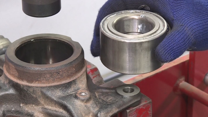
Installing the new wheel bearing into the knuckle (5:27)
Tip: Only remove the bearing from its protective packaging immediately before the fitting.
- This is to avoid ingress of dirt and therefore premature bearing failure.
- Use a suitable tool that comes in contact with only the end face of the outer ring.

Tip: Outer diameter of tool < outer diameter of bearing
- It is important to keep the bearing aligned to the knuckle bore and press it vertically into the knuckle.

Tip: Never press the inner ring to insert the bearing
- Make sure that the bearing is not inclined, and press it until correctly seated.
- Insert a new snap ring.
- Fix the dust cover to the knuckle.
- Support the hub, so that the shaft is vertical
- By using a suitable tool, push on the end face of the inner ring
- Press the bearing until seated against the indicated position.
Mounting the knuckle (7:00)
- Reassembly is the reverse of the dismounting process.
- Reattaching the knuckle to the lower suspension arm and strut

Tip: Torque settings can vary significantly between car models. Therefore check the manufacturer values.
- Attach the speed sensor.
- Attach the ball joint at the tie-rod end.
- Tighten the nut to the specified torque value.

Tip: In case the nut is rotating with the ball joint, press the ball joint further into the knuckle arm. The nut can now be tightened.
- Insert the split pin. Be sure to use a new one.
- After fitting the new nut by hand, tighten further with a socket to ensure the drive shaft is seated.
- The final torque setting will be done later when the car is on the ground.
Tip: The use of an impact wrench can result in demage of the CVJ internals
- Mount the brake disc and the brake caliper.

Tip: Ensure the brake hose has not be twisted or damaged.
- Mount the tyre and lower the car.
- Now the car is on the ground, the drive shaft nut can be tightened to the value specified by the manufacturer.
- Stake the nut into the groove of the shaft.
Tip:
- Depending whether the wheel is alloy or steel, there are various torque values and procedures. Please check carefully with the manufacturer`s instructions.
- Before driving, press several times on the brake pedal to ensure the brake pads come in contact with the brake discs.
- As the suspension has been disassembled, it is advisable to have the steering geometry checked.
