Dismounting of Outer Rings
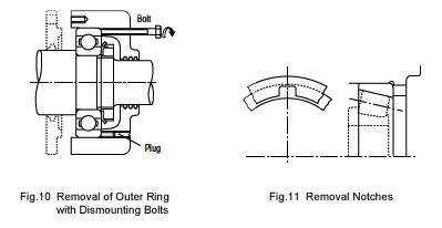
In order to remove an outer ring that is tightly fitted, first place bolts in the push-out holes in the housing at several locations on its circumference as shown in Fig.10, and remove the outer ring by uniformly tightening the bolts. These bolt holes should always be fitted with blank plugs when not being used for dismounting. In the case of separable bearings, such as tapered roller bearings, some notches should be made at several positions in the housing shoulder, as shown in Fig. 11, so the outer ring may be pressed out using a dismounting tool or by tapping it.

Dismounting of Bearings with Cylindrical Bores
If the mounting design allows space to press out the inner ring, this is an easy and fast method. In this case, the withdrawal force should be imposed only on the inner ring (Fig. 12). Withdrawal tools like those shown in Figs. 13 and 14 are often used.

In both cases, the claws of the tools must substantially engage the face of the inner ring; therefore, it is advisable to consider the size of the shaft shoulder or to cut grooves in the shoulder to accommodate the withdrawal tools (Fig. 14).
The oil injection method is usually used for the withdrawal of large bearings. The withdrawal is achieved easily by mean of oil pressure applied through holes in the shaft. In the case of extra wide bearings, the oil injection method is used together with a withdrawal tool.
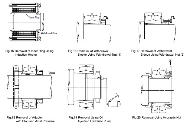
Induction heating is used to remove the inner rings of NU and NJ types of cylindrical roller bearings. The inner rings are expanded by brief local heating, and then withdrawn (Fig. 15). Induction heating is also used to mount several bearings of these types on a shaft.
Dismounting of Bearings with Tapered Bores
When dismounting relatively small bearings with adapters, the inner ring is held by a stop fastened to the shaft and the nut is loosened several turns. This is followed by hammering on the sleeve using a suitable tool as shown in Fig. 18. Fig. 16 shows one procedure for dismounting a withdrawal sleeve by tightening the removal nut. If this procedure is difficult, it may be possible to drill and tap bolt holes in the nut and withdraw the sleeve by tightening the bolts as shown in Fig. 17.
Large bearings may be withdrawn easily using oil pressure. Fig. 19 illustrates the removal of a bearing by forcing oil under pressure through a hole and groove in a tapered shaft to expand the inner ring. The bearing may suddenly move axially when the interference is relieved during this procedure so a stop nut is recommended for protection. Fig. 20 shows a withdrawal using a hydraulic nut.

| Related Pages |
|---|
